BMW 5 Series: Cold-start phase
Point A in the heat management module circuit diagram designates the cold start with an engine that has completely cooled down.
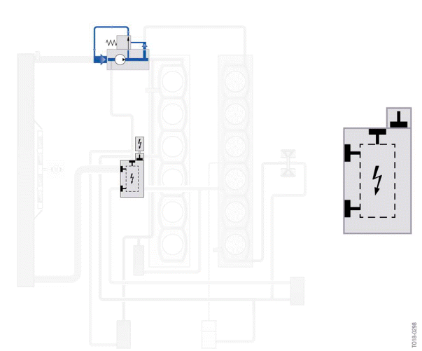
Cold-start phase, Bx8TU engine
In the cold-start phase, the coolant circulates exclusively via a bypass in the coolant pump. The rotary valve in the heat management module closes the coolant lines so that the excess pressure that builds up opens the pressure relief valve in the coolant pump (opening pressure 2.1 bar) and the coolant is recirculated in the coolant pump.
Because the coolant circuits through the exhaust turbocharger and the ventilation line of the cylinder head cannot be closed, a low volumetric flow is returned to the coolant pump here.
Warm-up phase
Area B in the circuit diagram for the heat management module shows the opening angle of the rotary valve in the warm-up phase.
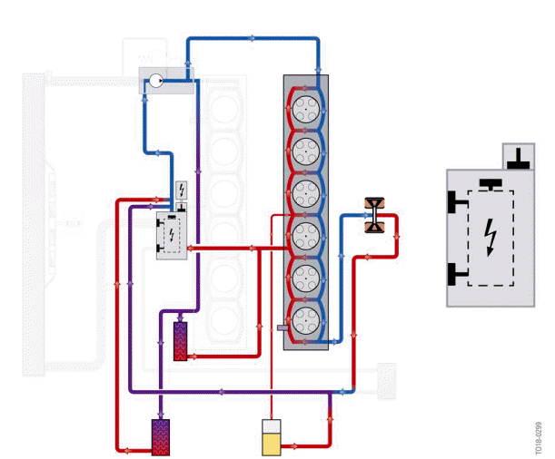
Warm-up phase, Bx8TU engine
In the warm-up phase, the heat management module additionally opens the connection to the heating in addition to opening the bypass line. The coolant flows through the cylinder head, the exhaust turbocharger and the engine oil/coolant heat exchanger. The electric split cooling valve is closed; no coolant flows through the engine block (split cooling).
READ NEXT:
 Operating temperature
The positions of the rotary valve at engine operating temperature are shown
by area C of the circuit
diagram.
Operating temperature, Bx8TU engine
The graphic shows control with the engine at operat
Coolant pump
The layout and function of the coolant pump have been revised and adapted to
match the cooling
concept of the Bx8 TU engines.
Coolant pump, Bx8TU engine
Pressure relief valve closed (pr
SEE MORE:
Recent destinations
General information
The previous destinations driven to are stored
automatically.
Open the destination from the
last destinations
1. Press the button on the
Controller.
2. "Recent destinations".
3. Select the destination.
Edit recent destinations
1. Press the button on the
Controller.
2. "Recen
Theater mode and
Individual Entertainment
General information
A selected entertainment source can be played
back in the rear via:
Individual Entertainment.
Theater mode.
Individual Entertainment
Regardless of the active entertainment source in
front, a separate entertainment source can be
played in the rear.
When Individual Entertain
