BMW 5 Series: Operating strategy of the heat management module
BMW 5 Series G30 2016-2026 Training Manual / B58TU Engine / Cooling System / Operating strategy of the heat management module
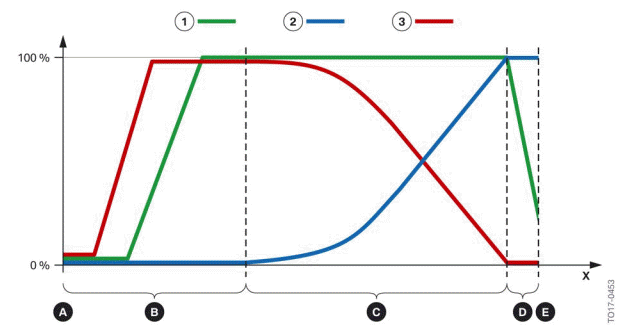
The following graphic shows the positions of the rotary valve as the coolant temperature increases.
Circuit diagram of heat management module in B58TU engine
0 % - Rotary valve closed
100% - Rotary valve open
- Cold start
- Warm-up phase
- Operating temperature
- Transition from normal operation to maximum cooling requirement
- Maximum cooling requirement
x - Rotational angle in angular degrees
- Heater circuit
- Main coolant circuit
- Minor coolant circuit
The openings on the rotary valve vary the cross-sections of the different coolant ducts as a function of the rotational angle of the rotary valve. The following graphics schematically represent the various engine operation phases, from cold start to maximum cooling requirement.
READ NEXT:
 Cold-start phase
Point A in the heat management module circuit diagram designates the cold
start with an engine that
has completely cooled down.
Cold-start phase, Bx8TU engine
In the cold-start phase, the coolant c
Operating temperature
The positions of the rotary valve at engine operating temperature are shown
by area C of the circuit
diagram.
Operating temperature, Bx8TU engine
The graphic shows control with the engine at operat
Coolant pump
The layout and function of the coolant pump have been revised and adapted to
match the cooling
concept of the Bx8 TU engines.
Coolant pump, Bx8TU engine
Pressure relief valve closed (pr
SEE MORE:
Exhaust turbocharger
B58TU exhaust turbocharger
Exhaust turbocharger in the B58TU engine
Exhaust turbocharger made of steel, for cylinder head-integrated exhaust
manifold ZIAK¹
Exhaust turbocharger made of steel, for non cylinder head-integrated
exhaust
manifold nZIAK²
ZIAK¹ = cylinder head-integrated exhau
Adaptive M chassis
Concept
The Adaptive M chassis is a controllable sport
chassis/suspension. This system reduces undesirable
vehicle motion when using a dynamic
driving style or traveling on uneven road surfaces.
This enhances the driving dynamics and driving
comfort depending on the road surface condition
and drivi
© 2019-2026 Copyright www.bmw5g30.com
