BMW 5 Series: xDrive
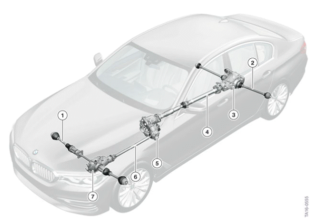
Overview of xDrive in the G30
- Output shaft, front
- Output shaft, rear
- Rear axle differential
- Drive shaft
- Transfer box
- Drive shaft
- Front axle differential
The designation of the transfer box is ATC13-1. The ATC13-1 is a standard transfer box and was first used in the G12.
One special feature of this transfer box is the Efficiency Mode introduced in the G12, which leads to a reduction of the splash losses and to reduce fuel savings. It was possible to adopt the measures introduced in G12 for the G30.
Oil change on the transfer box
The oil filling of the transfer box is designed for the entire unit service life. This corresponds to a mileage of approximately 150,000 km / 92,000 miles. A fault code entry with an oil change recommendation for the transfer box is stored when this mileage is exceeded.
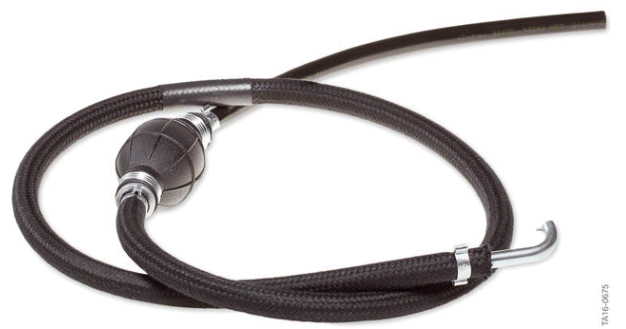
Suction hose with hand pump
Part number 83 30 0 493 337
The transfer box does not have an oil drain plug. The oil filling to be renewed must be drawn off using a hand pump via the opening of the oil filler plug.
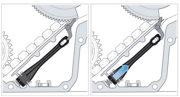
In order to ensure that the entire oil filling has been exchanged, the oil sump must remain open for the duration of extraction and filling.

The Service employee can move the oil sump to the open position by means of the "Service function > Transfer box VTG > Oil change" in the BMW diagnosis system ISTA.
Refer to the currently valid repair instructions for the exact procedure.
System wiring diagram
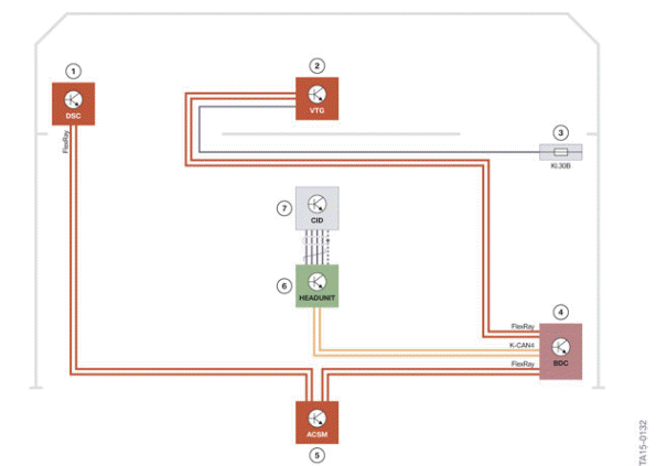
xDrive system wiring diagram in the G30
- Dynamic Stability Control (DSC)
- VTG control unit
- Power distribution box, front right
- Body Domain Controller (BDC)
- Advanced Crash Safety Module (ACSM)
- Head Unit
- Central Information Display (CID)
FlexRay - FlexRay bus
K-CAN4 - Body CAN4
READ NEXT:
 Voltage Supply and Bus Systems
Introduction
The electrical system of the new BMW 5 Series is based on the G12. The
following topic is described
in the Technical Reference Material for "ST1501 G12 Complete Vehicle".
Bus overview
Bus overview
ACC - Active Cruse Control also known as Long Range Radar sensor (LRR)
ACSM - Advanced Crash Safety Module
AMPT - Top HiFi amplifier
ASD - Active Sound Design
BDC - Body Domain Controlle
SEE MORE:
Deactivation criteria
The Lane Departure Warning is available at a speed range from 43 - 130 mph
(70 km/h - 210 km/h).
A warning is not issued in the following situations:
Use of the turn indicator
In construction zones
Lane is narrower than 8½ ft (2.60 m)
The warning is cancelled in the following
Drive-ready state
Switching on drive-ready state
Depress the brake pedal.
Press the Start/Stop button.
Switching off drive-ready state
Steptronic transmission:
1. Engage selector lever position P with the vehicle
stopped.
2. Press the Start/Stop button.
The engine is switched off.
3. Set the parking brake.
Au
