BMW 5 Series: Split cooling valve
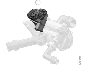
Heat management module with electric split cooling valve
- Electric split cooling valve
To guarantee optimal heat distribution during the cylinder head and crankcase warm-up, the coolant supply for the cylinder head and crankcase is controlled individually. The coolant is controlled by the Digital Motor Electronics (DME). The coolant is distributed by the electric split cooling valve on the heat management module in the warm-up phase such that substantially more coolant is available to the cylinder head than to the crankcase. Depending on the engine's operating condition, the Digital Motor Electronics (DME) decide on the distribution of the coolant quantity to the cylinder head and the crankcase as required.
Switching logic of split cooling valve

Switching logic of electric split cooling valve
- End stop
- Delivery position
- End stop
% - Valve opening in %
x - Rotary valve position in degrees, angle of rotation
- Rotary valve
The diagram shows the switching logic of the electric split cooling valve. Depending on the operating condition and coolant temperature of the engine, as well as the driver's desired load, the Digital Motor Electronics (DME) releases the coolant access from the crankcase to a greater or lesser extent via the rotary valve of the split cooling valve. The coolant now also flows through the crankcase and cools components.

A bleeding procedure in line with the repair instructions is required following a part exchange in the cooling system or refilling of the cooling system. Filling without a vacuum filler device (watering can filling) is not approved There is a risk of engine damage in case of failure to comply The filling specification must be observed Operation of the vehicle is not permitted without completing the entire filling and bleeding routine.
There is a risk of functional limitations or overheating.
READ NEXT:
 Heat management module
The function of the heat management module is similar to that of the heat
management module of the
B58 engine.
B58TU engine heat management module
Coolant output towards the coolant pump
Electri
Operating strategy of the heat management module
The following graphic shows the positions of the rotary valve as the coolant
temperature increases.
Circuit diagram of heat management module in B58TU engine
0 % - Rotary valve closed
100% - R
Cold-start phase
Point A in the heat management module circuit diagram designates the cold
start with an engine that
has completely cooled down.
Cold-start phase, Bx8TU engine
In the cold-start phase, the coolant c
SEE MORE:
System limits
Detection range
The detection capacity of the system and the
automatic braking capacity are limited.
Two-wheeled vehicles for instance might not be
detected.
Deceleration
The system does not decelerate in the following
situations:
For pedestrians or similarly slow-moving road
users.
For red tr
General information, Safety information
General information
The engine oil consumption is dependent on
your driving style and driving conditions.
Therefore, regularly check the engine oil level after
refueling by taking a detailed measurement.
The engine oil consumption can increase in the
following situations, for instance:
Sporty dr
