BMW 5 Series: Heat management module
The function of the heat management module is similar to that of the heat management module of the B58 engine.
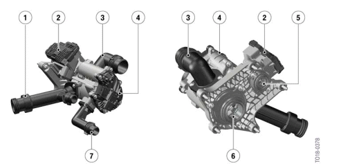
B58TU engine heat management module
- Coolant output towards the coolant pump
- Electric split cooling valve
- Coolant outlet to coolant radiator
- Electrical actuator, heat management module
- Coolant entry, split cooling valve
- Coolant entry, heat management module
- Coolant outlet, heating
A rotary valve inside the heat management module ensures needs-driven cooling of the various engine components. The opening cross-sections of the various coolant ducts can be opened or closed variably. A position sensor in the electrical actuator of the heat management module forwards the current position of the rotary valve to the Digital Motor Electronics (DME). The exact position of the rotary valve can thus be determined so that it opens or closes a precisely defined cross-section with respect to the various coolant ducts. Adjusting the cross-sections ideally adapts the flow rates of the coolant ducts connected to the heat management module to the engine operating points. To correctly position the rotary valve, the Digital Motor Electronics (DME) require information including the coolant temperature from the coolant temperature sensor, and the material temperature of the cylinder head from the component temperature sensor . Warm-up and cooling of the engine and the supply to ancillary components can be implemented as driven by requirements, thus optimizing consumption.
The following tables provide an overview of the technical data of the heat management modules:
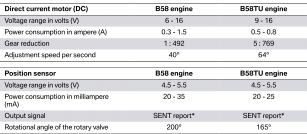
* SENT report = Single Edge Nibble Transmission
READ NEXT:
 Operating strategy of the heat management module
The following graphic shows the positions of the rotary valve as the coolant
temperature increases.
Circuit diagram of heat management module in B58TU engine
0 % - Rotary valve closed
100% - R
Cold-start phase
Point A in the heat management module circuit diagram designates the cold
start with an engine that
has completely cooled down.
Cold-start phase, Bx8TU engine
In the cold-start phase, the coolant c
Operating temperature
The positions of the rotary valve at engine operating temperature are shown
by area C of the circuit
diagram.
Operating temperature, Bx8TU engine
The graphic shows control with the engine at operat
SEE MORE:
Active seat ventilation
Concept
Integrated fans in the seat and armrest areas
provide a comfortable seat temperature.
Overview
Active seat ventilation
Switching on
Press the button once for each
ventilation
level.
The highest level is active when three LEDs are
lit.
The ventilation switches back by one level after a
sh
Stratification
On the G30 the stratification for the driver/front passenger is not adjusted
in the usual manner by the
knurled wheels on the front dash panel. Instead, there is a menu button located
in the center of the
IHKA control panel. Pressing this button opens the IHKA menu in the CID. Once
the menu is di
