BMW 5 Series: Split cooling
A new development for the B58TU engine is the split cooling. A cooling concept which is used the N63 TU2.
The split cooling function uses the electric split cooling valve, eSCV, to enable on-demand decoupling of the crankcase from the coolant flow both in the warm-up phase and in partial load operation. In this situation, the coolant is exclusively routed through the cylinder head. The engine reaches its operating temperature more quickly in the warm-up phase, and can be operated with reduced emissions in partial load operation.
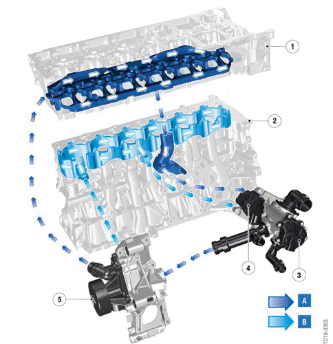
Cooling circuit, B58TU engine
- High cooling requirement, split cooling cylinder head
- Low cooling requirement, split cooling crankcase
- Cylinder head
- Crankcase
- Heat management module
- Electric Split Cooling Valve (eSCV)
- Coolant pump
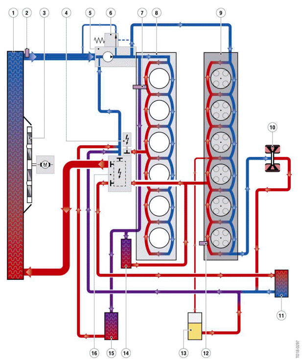
Cooling system for B58TU engine
- Coolant radiator
- Coolant temperature sensor, radiator outlet
- Electric fan
- Electric split cooling valve
- Coolant pump
- Pressure relief valve
- Coolant temperature sensor, crankcase
- Crankcase
- Cylinder head
- Exhaust turbocharger
- Heating
- Component temperature sensor
- Expansion tank
- Engine oil/coolant heat exchanger
- Transmission oil/coolant heat exchanger
- Heat management module
In split cooling, the cooling requirements for the crankcase and the cylinder head are managed by the electric split cooling valve. The fact that the engine reaches operating temperature more quickly again translates to substantial consumption and emission reductions.
READ NEXT:
 Split cooling valve
Heat management module with electric split cooling valve
Electric split cooling valve
To guarantee optimal heat distribution during the cylinder head and crankcase
warm-up, the coolant
supply fo
Heat management module
The function of the heat management module is similar to that of the heat
management module of the
B58 engine.
B58TU engine heat management module
Coolant output towards the coolant pump
Electri
Operating strategy of the heat management module
The following graphic shows the positions of the rotary valve as the coolant
temperature increases.
Circuit diagram of heat management module in B58TU engine
0 % - Rotary valve closed
100% - R
SEE MORE:
Selection lists
General information
Depending on your vehicle's equipment, the following
can be displayed or operated using the
buttons and the thumbwheel on the steering
wheel and via the displays in the instrument cluster
and the Head-up Display:
Current audio source.
Phone redial.
Activating a list and adjus
Functional principle
The system measures potential parking spaces when driving past at a speed
below approximately
22 mph (35 km/h) even without the system having been activated.
The parking spaces are measured by two additional ultrasonic sensors, which are
integrated into
the front wheel arch. Two additional u
