BMW 5 Series: System wiring diagram
B46/B58 Engine
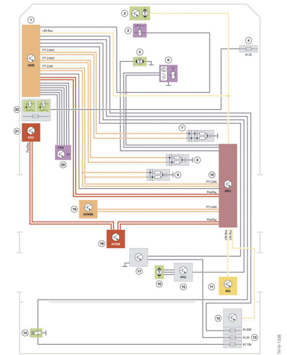
System wiring diagram B68/B58 engine in G30
- Digital Motor Electronics (DME)
- Electric fan
- Relay for electric fan
- Power distribution box, engine compartment
- Pinion starter
- Air conditioning compressor
- CAN terminator 6
- CAN terminator 5
- CAN terminator 4
- Body Domain Controller (BDC)
- Intelligent Battery Sensor (IBS)
- LIN interface
- Rear right power distribution box
- Electrical exhaust flap
- Fuel Pump Control (FPC)
- Electric fuel pump
- Tank leak diagnosis (Natural Vacuum Leak Detection NVLD)
- Advanced Crash Safety Module (ACSM)
- Instrument panel (KOMBI)
- Accelerator pedal module
- Dynamic Stability Control (DSC)
- Integrated supply module
N63TU2 Engine
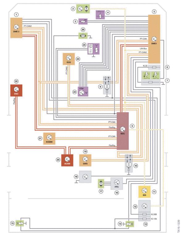
System wiring diagram N63TU2 engine in the G30
- Digital Motor Electronics (DME) 2
- Electric fan
- Temperature sensor
- Relay for electric fan
- Digital Motor Electronics (DME)1
- Power distribution box, engine compartment
- Integrated supply module
- CAN terminator 4
- Body Domain Controller (BDC)
- CAN terminator 5
- Intelligent Battery Sensor (IBS)
- LIN interface
- Rear right power distribution box
- Electrical exhaust flap, right
- Electrical exhaust flap, left
- Fuel Pump Control (FPC)
- Electric fuel pump
- Tank leak diagnosis (Natural Vacuum Leak Detection NVLD)
- Gear selector switch (GWS)
- Advanced Crash Safety Module (ASCM)
- Instrument panel (KOMBI)
- Dynamic Stability Control (DSC)
- Accelerator pedal module
- Electronic transmission control (EGS)
- Air conditioning compressor
- Pinion starter
READ NEXT:
 Air intake and exhaust emission systems
Air intake duct
In contrast to the 4- and 6-cylinder gasoline engines, the 8-cylinder
gasoline engine has a two-branch
intake system. This ensures that the necessary air volume is made available to
Active air flap control
It was possible to carry over the active air-flap control from the G12. The
cooling surfaces at the front
of the vehicle can be closed by means of two separate air flaps. This reduces
the drag coeff
SEE MORE:
Loading
Safety information
Warning
High gross weight can overheat the tires, damage
them internally and cause a sudden drop in
tire inflation pressure. Driving characteristics
may be negatively impacted, reducing lane stability,
lengthening the braking distances and
changing the steering response. There is
Buttons for the central
locking system
General information
In the event of a severe accident, the vehicle is
automatically unlocked. The hazard warning system
and interior lights come on.
Overview
Buttons for the central locking system.
Locking
Press the button with the front
doors
closed.
The fuel filler flap remains unlocked.
The
© 2019-2026 Copyright www.bmw5g30.com
