BMW 5 Series: Setting the speed
Maintaining and storing the speed
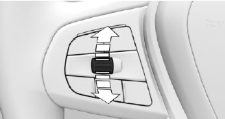
Press the rocker switch up or down once while the system is interrupted.
When the system is switched on, the current speed is maintained and stored as the desired speed.
The stored speed is displayed in the speedometer and briefly in the instrument cluster.
DSC Dynamic Stability Control is switched on, if necessary.
The speed can also be stored by pressing a button.
.png) Press the button.
Press the button.
Changing the speed
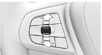
Press the rocker switch up or down repeatedly until the desired speed is set.
If active, the displayed speed is stored and the vehicle reaches the stored speed when the road is clear.
- Each time the rocker switch is pressed to the resistance point, the desired speed increases or decreases by 1 mph/1 km/h.
- Each time the rocker switch is pressed past the resistance point, the desired speed changes by a maximum of 5 mph/10 km/h.
Hold the rocker switch in position to repeat the action.
READ NEXT:
 Adjusting the distance
Safety information
Warning
The system cannot serve as a substitute for the
driver's personal judgment. Due to the system
limits, braking can be late. There may be a risk
of accident or risk of damage
Displays in the instrument
cluster
Display in the speedometer
Green marking: system is
active,
the marking indicates the
desired speed.
Orange/white marking: system
is interrupted, the marking indicates
the stored speed.
No m
System limits
Detection range
The detection capacity of the system and the
automatic braking capacity are limited.
Two-wheeled vehicles for instance might not be
detected.
Deceleration
The system does not deceler
SEE MORE:
24 V Electronic Power Steering
The greater weight of the engines in the G30 on vehicles with 8-cylinder
engines results in a higher
front axle load. This has the effect that the required power of the steering
assist increases. Due to
these high currents, it is necessary to increase the voltage supply of the EPS
to 24 V.
Overview of exterior camera operating menu
Once the camera systems have been activated successfully, the driver has the
option of selecting the
appropriate view or camera via iDrive.
G30 Switch block with Panorama View button
Parking assistance button
Panorama View button
The camera systems can be activated (depending on the vehicle eq
© 2019-2026 Copyright www.bmw5g30.com
